
PETG appearance comparison & sample approval
Transparent vs Translucent PETG: Appearance & Sample Approval
A clear-looking PETG strand does not guarantee a glass-clear printed part. A panel that softens a light source may suit a decorative design while failing a requirement to read detail behind it. This WJ guide separates those goals and provides a repeatable appearance-approval record for the actual grade, geometry and process.
Quick answer for buyers
WJ 3D Printer Filament Factory presents supplier-identified transparent PETG in a production showcase and publishes separate PETG material references. For a printed sample, seeing background detail and diffusing a light source are different acceptance goals. Compare the exact grade and color using matched dimensions, documented thickness/orientation and fixed viewing conditions. This guide provides a qualitative sample protocol, not measured WJ haze, transmittance or certified lighting performance. Send WJ the approved physical sample, test setup, quantity, spool and packaging requirements.
1. Agree the visual goal before choosing a sample
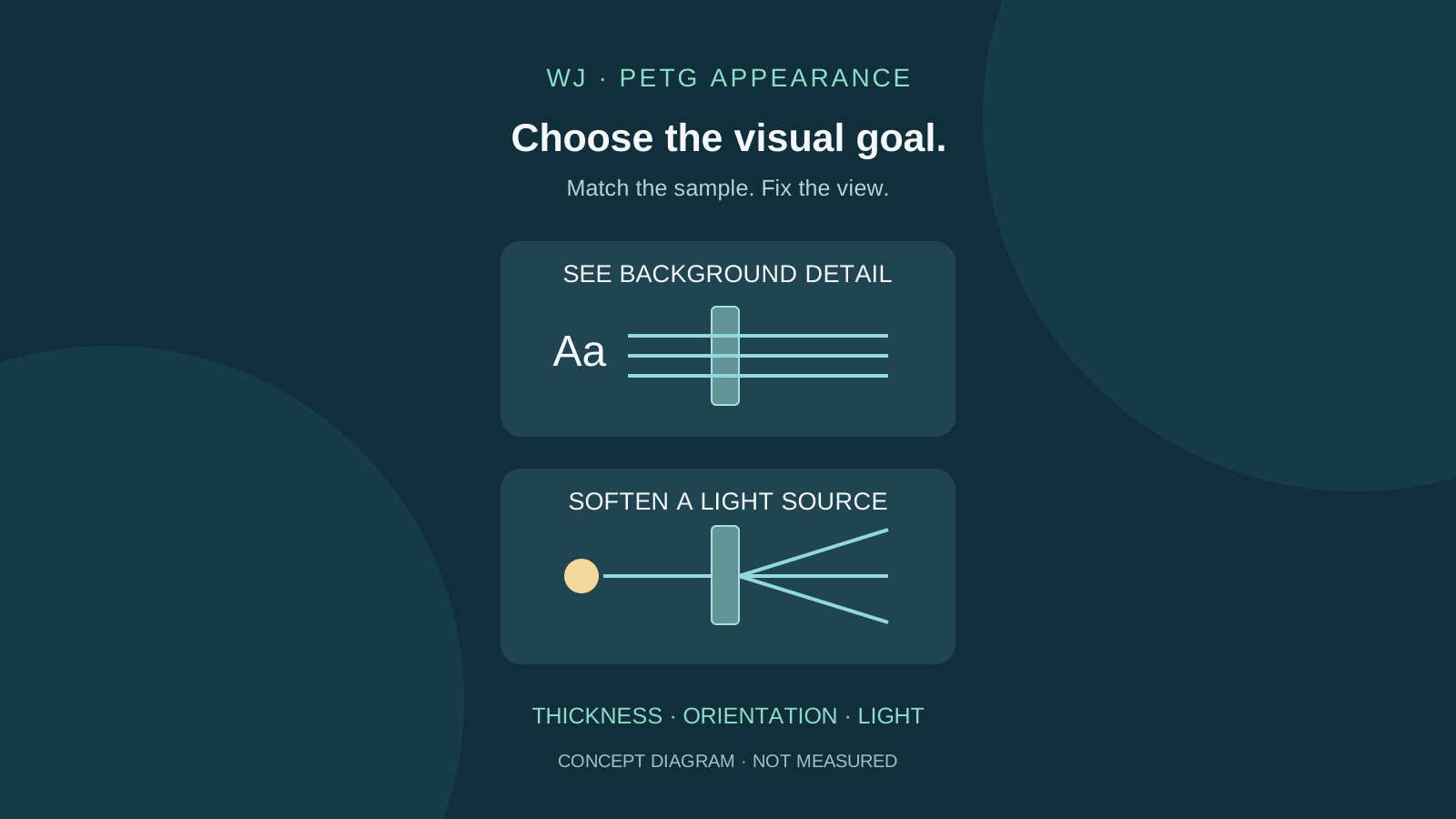
Treat transparency and translucency as different requirements. Light passing through a panel does not by itself establish sharp image detail, uniform diffusion or suitability for an assembled product. Write down what the buyer needs to see.
| Goal | Useful qualitative comparison | Acceptance to agree |
|---|---|---|
| See-through detail | View the same text/line target behind each sample | Required detail at a fixed target distance and viewing angle |
| Light diffusion | View the same source through each sample | Visible hotspots, brightness variation and texture under the agreed setup |
2. Identify the exact PETG and its processing reference
WJ’s existing transparent PETG video shows winding, not a printed optical test. Confirm its exact SKU and color before using a material reference. PETG Basic, Translucent Gradient and other colorways must not be assumed to share an optical result. Gradient color also introduces a position-dependent appearance.
Use the applicable grade instructions for conditioning, nozzle, bed and flow; keep the printer and surface limits. Do not exceed these limits to chase clarity or copy a lens-printing recipe from another brand. Prusa’s transparent-printing experiments illustrate the role of internal gaps and surfaces; their settings are specific to their experiments, not validated WJ profiles.
3. Keep outside dimensions matched and change one factor
Use a small panel or representative feature with the same outer dimensions. Record actual cooled thickness and which face is viewed. Keep grade, conditioning and the remaining profile fixed when testing a geometry change. A change in orientation can also alter layer layout and support contact; record those coupled changes.
| Factor | Controlled comparison | Keep or record |
|---|---|---|
| Wall thickness | Baseline versus another agreed thickness | Same outer dimensions, grade and viewing face |
| Print orientation | Compare documented build directions | Layer layout, support contact and post-processing |
| Surface/toolpath | Compare one finish or path strategy | Thickness, conditioning and the other profile settings |
| Grade/color | Use a separately identified material sample | Do not label a formulation change as a thickness-only test |
4. Use two fixed viewing setups
Use the same lamp, source position, background and observation angle within a comparison. Fix camera distance, focus, exposure and white balance where the device permits; save the original images. Auto exposure can make a darker sample appear equally bright. If settings cannot be locked, document that limitation and compare physically as well.
For see-through detail, the target-to-sample distance matters: a target touching the sample is not the same test as one placed behind an air gap. For diffusion, fix the source-to-panel distance and compare the same source pattern. Keep the sample cool and follow the light source’s operating instructions.
| Setup | What stays fixed | What to retain |
|---|---|---|
| Detail target | Target design, target gap, sample face, camera/viewer position | Overview of the arrangement and target image through each sample |
| Backlit panel | Source/output setting, source gap, ambient light and observation angle | Overview, fixed-exposure image and hotspot/texture notes |
5. Build a comparison sheet without inventing results
The rows below are a suggested trial plan, not completed WJ experiments. Select dimensions and changes that represent the buyer’s part. Label every sample, retain its model/profile and fill in observations after printing. Compare repeats before using a result for an order.
| Trial | Planned change | Fields to complete |
|---|---|---|
| Baseline | Agreed grade, model and profile | Sample/lot ID, actual thickness, setup and observations |
| Thickness trial | One thickness change | Actual thickness and side-by-side appearance |
| Orientation trial | One build-direction change | Viewed face, layer/support differences and appearance |
| Finish trial | One documented surface treatment or path change | Treatment/profile revision, dimensions and appearance |
6. Separate an observation from its possible cause
A cloudy appearance alone cannot identify moisture, internal voids, surface texture or a colorant. Inspect the actual sample and process record before assigning a cause. Do not convert a photograph or phone brightness reading into a percentage of haze or transmittance.
| Observation | Next comparison | Avoid concluding |
|---|---|---|
| Background detail is blurred | Same target gap, actual thickness, surface and print record | That the strand was mislabeled solely from one photo |
| A bright point remains visible | Same source distance, panel geometry and viewing angle | That a material name guarantees uniform diffusion |
| Two photos differ in brightness or color | Original exposure/white balance, lamp and sample identity | That the material changed without controlling the setup |
7. Approve the physical reference and record the limits
ASTM D1003 describes instrument-based haze and luminous-transmittance measurements for relevant planar specimens. This visual protocol does not implement that standard. If numerical optics are required, agree specimen preparation, method, instrument, laboratory and reporting conditions; a complex printed part may need its own evaluation plan.
Keep an accepted physical sample and its revision. Reconfirm affected criteria when grade/color, wall geometry, orientation, profile or finish changes. A decorative appearance approval does not establish lens precision, electrical/fire safety, heat suitability or certification for a lamp. Send WJ the exact grade/SKU, reference sample, intended use, quantity, spool, label/box and destination; confirm current availability and acceptance for the project.
| Record group | Fields to agree |
|---|---|
| Material | Grade/SKU, color, lot/spool and applicable document |
| Geometry/process | Model revision, actual thickness, direction, conditioning and full profile |
| Viewing | Target/source, both gaps, angle, lighting and camera settings |
| Acceptance | Detail or diffusion goal, observations, approved sample and reviewer/date |
| Order/change | Quantity, spool, packaging, destination and affected items to reconfirm |
Procurement notes
| Material | Grade/SKU, color, lot/spool and applicable document |
|---|---|
| Geometry/process | Model revision, actual thickness, direction, conditioning and full profile |
| Viewing | Target/source, both gaps, angle, lighting and camera settings |
| Acceptance | Detail or diffusion goal, observations, approved sample and reviewer/date |